The various components of robot vacuum cleaners, such as the main roller brush, side brush, dustbin, and sensor housing, have different requirements for material selection, mold design, and process parameters in injection molding due to their distinct functions. This article will delve into the injection molding processing points of these key components, starting from their processing procedures.
1. Material Selection: Matching Component Functional Requirements
The functional characteristics of different components determine the choice of injection molding materials, which need to balance core indicators such as strength, wear resistance, and lightweight properties.
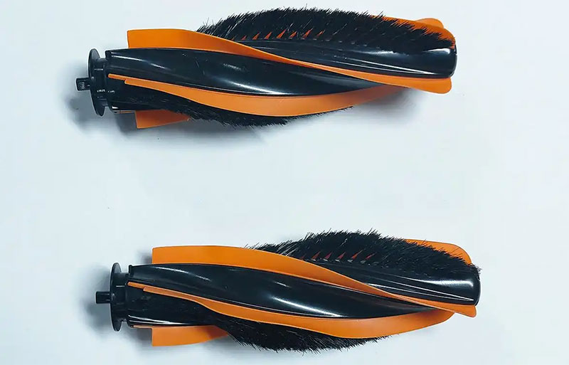
Main Roller Brush Frame and End Cap
The main roller brush has to withstand high-speed rotation (usually 1500 – 3000 revolutions per minute) and ground friction. The frame is made of high-strength ABS (impact strength ≥ 20 kJ/m²) to ensure it does not deform under long-term stress. The end cap comes into contact with the roller shaft and requires excellent wear resistance, so it is made of POM (friction coefficient ≤ 0.3) to reduce wear and noise during operation.
Side Brush Base and Mounting Plate
The side brush frequently touches corners and obstacles. The brush base is made of fatigue-resistant PP (flexural modulus ≥ 1500 MPa) to withstand repeated deformation. The mounting plate needs to hold the bristles firmly, so it is made of glass-fiber-reinforced PA66 (containing 15% – 20% glass fiber) to enhance its resistance to centrifugal force and prevent cracking during high-speed rotation.
Dustbin and Cover Plate
The dustbin needs to be lightweight and resistant to stains. Food-grade PP (density 0.9 g/cm³) is selected for its ease of cleaning and low cost. The hinge structure of the cover plate requires toughness, so a PP and EPDM blend material is used to ensure it does not break after more than 10,000 opening and closing cycles.
Sensor Protective Cover
The protective covers for laser radar or infrared sensors require high light transmittance. Optical-grade PC (light transmittance ≥ 89%) is chosen, and anti-ultraviolet additives are added to prevent yellowing after long-term use.
2. Mold Design: Adapting to Component Structural Characteristics
The structural complexity of components demands precise mold design, with a focus on the following aspects:
Main Roller Brush Frame Mold
The surface of the frame has evenly distributed bristle fixing slots (with a spacing of 0.5 – 1 mm). The mold cavity needs to achieve high-precision slot positions through electrical discharge machining (EDM), with a tolerance control within ±0.02 mm to ensure neat bristle arrangement after implantation. To avoid the influence of weld lines on strength during injection molding, the mold adopts a hot runner system, with the gate placed at both ends of the frame so that the melt flows from both ends towards the middle, reducing the formation of weld lines.
Side Brush Mounting Plate Mold
The mounting plate has radially distributed bristle holes (with a diameter of 0.3 – 0.5 mm). The mold needs to be designed with fine cores, and the diameter error of the core rods should be ≤ 0.01 mm to prevent hole blockage or misalignment. Since the mounting plate is relatively thin (1 – 1.5 mm thick), the mold cooling system uses conformal cooling channels that closely follow the cavity surface to ensure uniform cooling and prevent warping.
Dustbin Mold
The dustbin has a thin-walled structure (wall thickness 1 – 1.2 mm). The mold needs to be made of high-speed injection molding special steel (such as 718H), and the surface should be polished to a mirror finish (Ra ≤ 0.02 μm) to reduce the flow resistance of the melt. To ensure airtightness, the sealing groove on the edge of the dustbin (for placing the silicone ring) needs to be formed in one piece, with a slot width tolerance controlled within ±0.05 mm to prevent dust leakage.
Sensor Protective Cover Mold
The protective cover requires no scratches or bubbles. The mold cavity needs to be ultra-finely polished (reaching A3-grade mirror finish) and equipped with special vent slots (with a width of 0.01 mm) to prevent gas retention and the formation of pinholes. The gate adopts a submarine design to avoid leaving gate marks on the appearance surface.
3. Process Parameters: Targeted Optimization of the Molding Process
According to the material and structure of components, the injection molding process parameters need to be precisely adjusted:
Main Roller Brush Frame (ABS)
The barrel temperature is controlled in sections (front section 200 – 210°C, middle section 210 – 220°C, nozzle 210 – 215°C). The injection pressure is 80 – 100 MPa, the holding pressure is 60 – 70 MPa, and the holding time is 10 – 15 seconds to ensure a dense frame without shrinkage marks. Due to the relatively long length of the frame (20 – 30 cm), a low filling speed (50 – 60 mm/s) is used to avoid uneven melt flow and warping.
Side Brush Mounting Plate (Glass-Fiber-Reinforced PA66)
The barrel temperature needs to be increased (250 – 260°C) to reduce the melt viscosity. The injection pressure is 100 – 120 MPa to ensure that the melt fills the fine bristle holes. Meanwhile, the back pressure is set to 3 – 5 MPa to promote the uniform dispersion of glass fibers and reduce the strength reduction caused by fiber agglomeration.
Dustbin (PP)
High-temperature, high-pressure, and rapid molding is adopted. The barrel temperature is 180 – 200°C, the injection pressure is 70 – 80 MPa, and the filling speed is 80 – 100 mm/s to shorten the residence time of the melt in the cavity and prevent insufficient filling in thin-walled areas due to rapid cooling. The cooling time is controlled at 15 – 20 seconds to ensure no deformation during demolding.
Sensor Protective Cover (Optical-Grade PC)
The melt temperature needs to be strictly controlled (280 – 300°C) to prevent material degradation and yellowing due to excessive temperature. The injection speed is controlled in sections (slow at the front section 30 – 40 mm/s, fast at the middle section 60 – 70 mm/s, and slow at the back section 20 – 30 mm/s) to reduce the internal stress generated by the melt impacting the cavity and prevent cracking in the later stage.
4. Post-Processing and Quality Inspection
After molding, components need to undergo post-processing to improve their performance and undergo strict inspection of key indicators:
Stress Relief Treatment
The PC sensor protective cover needs to undergo annealing treatment (holding at 120°C for 2 hours) to eliminate the internal stress generated during injection molding and prevent cracking during use.
Surface Treatment
If the main roller brush frame needs to be wrapped with TPE soft rubber, its surface needs to be plasma-treated to improve the bonding strength with TPE (peel strength ≥ 5 N/cm).
Quality Inspection
- Dimensional Inspection: Use a coordinate measuring machine to inspect the straightness of the main roller brush frame (≤ 0.1 mm/m) and the dimensions of the sealing groove on the dustbin (within an error of ±0.03 mm).
- Appearance Inspection: Use visual inspection equipment to screen for scratches (depth ≤ 0.01 mm) and bubbles (diameter ≤ 0.1 mm) on the surface of the protective cover.
- Performance Testing: Conduct fatigue testing on the side brush (continuous rotation for 500 hours) to check for cracking. Conduct airtightness testing on the dustbin (holding pressure at 0.2 MPa for 30 seconds, with a leakage amount ≤ 1 kPa).
5. Process Stability Control in Mass Production
To ensure consistency in large-scale production, a comprehensive process control system needs to be established:
Material Pre-Treatment
Hygroscopic materials (such as PA66 and PC) need to be pre-dried (PA66 at 80 – 90°C for 4 hours, PC at 120°C for 6 hours) to reduce the moisture content to ≤ 0.02% and prevent the formation of bubbles during injection molding.
Equipment Monitoring
Use intelligent injection molding machines to monitor the barrel temperature (fluctuation ≤ ±1°C) and injection pressure (fluctuation ≤ ±2 MPa) in real-time, and automatically alarm in case of abnormalities.
Mold Maintenance
After every 100,000 mold cycles, polish and repair the mold cavity and core to ensure stable surface quality of components. Regularly clean the hot runner nozzle to prevent material blockage.
Conclusion
The injection molding processing of components for robot vacuum cleaners requires a precise match among “materials, molds, and processes.” Each step, from material selection to mass production, needs to be optimized around the functional characteristics of the components. By using high-strength materials to ensure durability, precision molds to control structural accuracy, and targeted process parameters to reduce defects, combined with strict quality inspection, high-quality components that meet cleaning efficiency, service life, and user experience requirements can be produced. As robot vacuum cleaners develop towards lightweight and intelligent directions, injection molding will further integrate with technologies such as two-color molding and in-mold assembly to continuously upgrade component performance.