Although every product is unique, the following design tips represent the ‘best practices’ that have been derived from decades of practical experience within the plastic injection molding industry. Product developers are well-advised to consider these guidelines for the following common design features.
- Bosses
A boss is a stressed point of engagement, shaped like a post or pillar. It’s usually the place where a screw will hold two parts of a case together.
A boss is a relatively large mass of plastic resin. Whenever there is such a mass, it will be the focus of thermal stress as this area cools after injection. The designer needs to mitigate this effect by following these rules:
Put a radius at the base, sized between 25-50% of the wall thickness
Attach the boss to an adjacent external wall using a rib
Strengthen the base with gussets for high-stress applications
Limit the height to no more than 3X the outside diameter
Use a draft angle on the outside of 1/2°. A smaller draft can be used inside the hole of the boss if the tool and core have been well-polished
Locate multiple bosses no closer than twice the distance of the adjacent wall thickness
- Ribs
A rib is a short wall on the cavity side of a molded part. They increase stiffness without adding too much mass if designed correctly.
Make ribs no thicker than 50% of the wall thickness they attach to
Radius of the base, between 25-50% of the wall thickness
Limit the height to no more than three times wall thickness
Increase the draft angles to allow for easier release
Gussets are similar to ribs but are smaller and are used to strengthen the base of a feature without attaching to a wall. The same design rules for ribs also apply to gussets.
- Corners
Avoid sharp inside and outside corners because they concentrate too much stress on the joint.
Radiused corners dissipate this stress over a larger surface area, and they also make it easier to fill during the injection.
Make the inside radius at least 50% of the wall thickness
Make the outside radius of a wall section equal to the inside radius and wall thickness
- Draft angles
Draft angles are an essential design feature for finished parts and mold tools.
They create a separation between the part feature and the tool wall, so the part can be released from the mold cleanly and without damage. We strongly recommend discussing draft angles with the mold maker and manufacturer for specific designs, but these general rules apply.
Use a minimum clearance of 1/2°, with 1° being preferable
Increase draft angles for rough surface textures
Use right-angle inserts inside the mold tool to create true 90° walls
The draft angle may need to be adjusted based on the type of resin, any fillers used in the resin, and the mold steel
- Ejector pins
Ejector pin design is an important part of the overall tooling strategy.
The tooling engineer needs to distribute the pushing force over a large surface area, by using multiple pins of different sizes and shapes. Especially thin features are a challenge because those areas are fragile and there’s very little material to push against.
When a pin pushes the part out of the mold, it leaves behind a characteristic shallow mark on the part. In most cases, this mark can’t be avoided but it can be managed.
Design pin locations so that the mark is in an unobtrusive area
Incorporate the ejector pin mark into the part design if possible
Some part shapes can be ejected by using stripper plates instead of pins
- Gates
A gate is a location where liquid resin enters the mold cavity.
The first priority here is to choose a location that fills the mold completely and with full packing density before the resin solidifies and the gate freezes off. Achieving this goal, therefore, requires balancing out the size, shape, and location of the gate(s) with the geometry of the part.
We can’t anticipate every possible gating solution, but there are some general best practices.
Locate gates so they fill thicker sections before thinner ones
Arrange multiple gates to distribute material evenly throughout the runner system
Gate witness marks can be mitigated by hiding them in the part design
- Holes
Holes are made with core pins.
They define the size and shape of the hole and provide cooling. One potential problem is that high injection pressures and temperatures can cause holes to be deformed, so employ these design tips.
For blind holes, make the hole depth no more than twice the hole diameter
For through holes, the length-to-width ratio can be increased to 4X
For holes above 5 mm in diameter, the maximum ratio is 6X
The distance between adjacent holes, or a hole and the part edge, should be 2X the wall thickness or 2X the hole diameter, whichever is greater
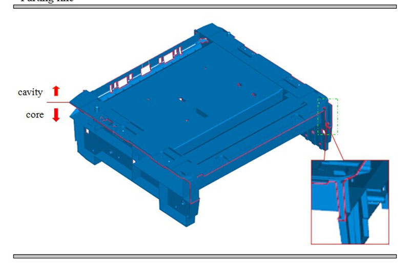
- Parting lines
This is the line where the two halves of a mold tool separate to release the part from a single large cavity.
A corresponding line may be left behind on the part which is often unavoidable. Here are some tips for good design.
Incorporate the parting line into the cosmetic design of the part to camouflage it
If there are recessed holes near the parting line, design them so that the opening act of the tool helps to create the hole, rather than requiring extra inserts or side actions
- Texture
Heavily textured or coarse surfaces on mold tools may cause them to grip the surface of the corresponding plastic part as it cools.
This can cause scratching or, worse, part breakage when trying to remove the part from the mold.
Increase draft angle with increased depth of texture
Taper the texture at a wall’s edge to provide additional release
- Shrinkage
One of the most difficult variables to control in plastic injection molding is the shrink rate of the plastic resin.
This rate is dependent on the resin chemistry, fillers, or additives in the resin, and the geometry of the part features. Product designers should communicate closely with the tooling engineer to optimize these key areas.
Keep wall thicknesses to a minimum
Keep adjacent wall surfaces equal in thickness. When this isn’t possible, create a transition from one wall to another using a gradient of 3:1
When possible, core out thick sections of walls or other features to reduce thermal mass
Orient thicker wall sections closer to gates and runners, so that these areas fill first before thinner sections
Plastic in contact with the tool wall should be as uniform in thickness as possible
For more information on the typical shrinkage rates of common resins, consult our chart of shrinkage rates over a range of sizes. These values are generally well known to the manufacturer and can be managed through good process control.
- Weld Lines
Where two flow fronts of liquid resin meet inside the tool and re-form, they tend to create a characteristic weld line that’s visible on the surface.
This is especially a concern wherever the resin is forced to go around some obstruction in the tool, such as a post used to make a hole. Weld lines are not just unsightly but they can also weaken the part.
Weld lines may be unavoidable in many cases but they can be managed in the following ways.
Create more cooling circuits in the area where weld lines form
Camouflage the weld line within the design
Move gate locations or add additional gates
Use rough surfaces to disguise the weld line
We’ve covered the main areas that designers should apply to plastic injection molded parts in this article. Of course, since every project is unique, you should work closely with your manufacturing partner to find realistic solutions to help you meet your product development goals.