Abstract
Weld lines are an extremely common defect in injection-molded parts, manifesting as linear or V-shaped groove-like marks at the confluence where molten resin flows around obstacles (such as inserts, holes, or multiple gates) in the mold cavity. These marks not only mar the appearance but also weaken the interfacial strength. Their causes encompass various factors, including low melt temperature, improper injection/packing parameters, inadequate mold venting/cooling design, and defective product structural design. This article will provide a detailed analysis of the formation mechanism, main impacts, and eleven major categories of solutions for weld lines in the following sections, along with a brief outlook on typical application cases and cutting-edge technologies, aiming to offer a comprehensive reference for optimizing injection molding processes.
I. Definition and Manifestation of Weld Lines
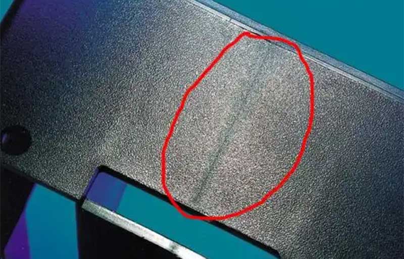
Weld lines, also known as confluence lines, mold-closing lines, or joining lines, refer to visible defects that occur when two or more streams of molten resin in an injection mold cavity fail to fully fuse at the confluence of different flow channels. Typical manifestations include:
Appearance
- Visible linear, V-shaped, or wavy fine lines on the surface; particularly prominent in transparent or light-colored plastics.
Mechanical Properties
- Incomplete bonding at the confluence results in a significant decrease in impact strength, tensile strength, and fatigue life.
In addition to affecting aesthetics and performance, weld lines can also serve as stress concentration points, reducing the safety of plastic parts during use. Therefore, they require focused attention during the design and production stages.
II. Main Causes of Weld Lines
The formation of weld lines is the result of multiple factors working in tandem. Common causes can be summarized into the following categories:
1. Low Melt and Mold Temperatures
- Low barrel/nozzle temperatures, low mold temperatures, or slow injection speeds can cause the leading stream of melt to partially solidify during flow, preventing full fusion upon confluence and resulting in visible joining lines.
2. Improper Injection and Packing Parameters
- Insufficient injection or packing pressure fails to continuously apply pressure at the interface, leading to void formation after melt shrinkage.
- Short packing times make it difficult to compensate for cooling shrinkage, affecting bonding strength.
3. Inadequate Venting
- If the confluence point is at the end of the flow path and no vent slots or vent holes are provided, air cannot escape in a timely manner, resulting in gas burning and scorching, which exacerbates the weld line defect.
4. Improper Gate and Runner Design
- Uneven distribution of multiple gates or an excessively small runner cross-section can cause inconsistent pressure and significant flow rate differences among the melt branches, preventing smooth fusion at the confluence.
5. Product Structure and Wall Thickness Design
- Drastic changes in wall thickness (e.g., excessive differences between thin and thick sections) and frequent distribution of holes or inserts can cause the melt to split and rejoin when flowing around obstacles, forming weld lines.
III. Detection and Evaluation of Weld Lines
Visual and Magnifying Glass Inspection
- The most intuitive method, suitable for preliminary defect localization, but difficult to quantify.
Microscopic Analysis
- Allows observation of surface and interfacial microstructures to analyze the degree of melt fusion.
Mechanical Testing
- Compares the impact and tensile strength differences between the weld area and the base material to evaluate performance impacts.
CT Scanning or Sectional Microscopy
- Used to detect the presence of air pockets or irregular voids within the confluence interface.
IV. Solutions for Weld Lines
In response to the above causes, countermeasures can be implemented at the material, process, mold, and design levels.
A. Material Optimization
- Select high-flow resins to reduce melt viscosity.
- Adjust additive formulations (e.g., lubricants, plasticizers) to enhance melt flowability.
- Strictly dry hygroscopic resins to avoid moisture-induced melt stratification and bubbles.
B. Process Parameter Adjustment
- Increase melt and mold temperatures: Gradually raise the barrel, nozzle, and mold temperatures to improve melt fusion and shorten cooling times.
- Increase injection and packing pressure/time: Ensure continuous pressure application at the interface to compensate for shrinkage and enhance bonding strength.
- Optimize injection speed: Accelerate filling speed while avoiding jetting marks to reduce the time for melt semi-solidification.
- Adopt staged injection or pulsed packing: For special large parts or thin-walled components, control flow and pressure in stages to balance molding conditions.
C. Mold and Runner Design
- Optimize gate type and location: Prefer single-point gates or relocate weld lines to inconspicuous areas.
- Enlarge runner and gate cross-sections: Reduce melt flow resistance to maintain higher flow front temperatures and more uniform pressure.
- Add vent slots/vent pins: Especially at confluence endpoints, to ensure smooth air escape and prevent burning.
- Local temperature control: Install independent heating or cooling circuits in the fusion zone to achieve temperature balance or local heating.
D. Product Structure Optimization
- Uniform wall thickness design: Avoid excessive differences between thin and thick sections to reduce unnecessary flow splitting.
- Minimize unnecessary holes and inserts: If holes are required, consider flow compensation or wall thickening in the design.
- Utilize reinforcing ribs: Add local thin ribs around the fusion zone to alter flow paths and confluence shapes, shifting defects to non-functional areas.
V. Typical Cases and Practical Experience
Consumer Electronics Panel
- By relocating the gate from the center of the panel to the side and adding vent slots at the confluence area, the appearance of weld lines improved by over 80%.
Automotive Instrument Frame
- Installing small heating elements in locally cold cavity areas and raising the local temperature by 20°C increased the weld line strength to over 90% of the base material strength.
Large Washing Machine Shell
- Adopting structural foam injection molding to reduce wall thickness differences and combining it with pulsed packing technology significantly reduced the depth of weld lines in thick-walled areas.
VI. Future Development Trends
Intelligent Monitoring
- Utilize online sensors and AI algorithms to monitor melt temperature, pressure, and flow rate in real time, automatically optimizing parameters to prevent weld lines.
Advanced Material Applications
- Develop novel ultra-high-flow resins and functional composite materials to reduce weld sensitivity.
Visual Mold Flow Simulation
- Accurately predict confluence locations during the mold design stage and achieve “zero-defect” positioning through virtual optimization.
Micro and High-Precision Injection Molding
- With the development of micro-injection molding and microstructure technologies, weld line control will advance toward nanoscale bonding interfaces.
By implementing these systematic strategies, injection molding companies can not only significantly improve weld line defects but also enhance overall product quality and production efficiency, meeting the increasingly stringent appearance and performance requirements of high-end plastic parts.