Nylon (PA, polyamide), as a key member of engineering plastics, is widely used in automotive, electronics, machinery, and other fields due to its excellent mechanical properties and processing adaptability. The amide groups in its molecular structure endow the material with unique crystallization characteristics. Precise control of crystallinity, orientation, and process parameters during processing is crucial for achieving high-quality nylon products. This article systematically analyzes the core technologies and practical considerations of nylon injection molding from the perspective of material properties.
I. Nylon (PA) Material Properties: From Molecular Structure to Performance Advantages
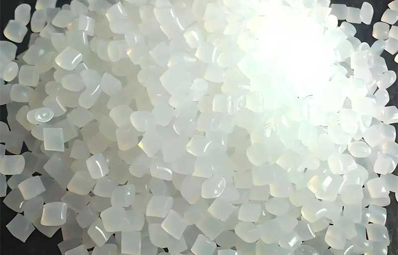
(I) Family Classification and Crystallization Characteristics
PA is a class of linear polymers containing amide groups. Common types include aliphatic nylons such as PA6, PA66, and PA46, all of which exhibit high crystallization capabilities. The polar amide groups in their molecular structures readily form hydrogen bonds, facilitating the crystallization process. Processing conditions (e.g., cooling rate and shear action) directly influence crystallinity, which can vary by up to 40%:
- Rapid cooling: Low crystallinity (~30%), resulting in good toughness but insufficient strength.
- Slow cooling: High crystallinity (up to 70%), enhancing rigidity but increasing brittleness.
Additionally, shear flow induces molecular orientation, leading to anisotropic properties in the molded part, with strength increasing by 20%-30% along the orientation direction.
(II) Core Performance Advantages
Mechanical Properties:
- Excellent toughness (notched impact strength: 50-100 kJ/m²) and wear resistance (abrasion loss: 0.01-0.05 mm³), making it suitable for moving parts such as gears and bearings.
- Wide service temperature range (-40°C to 100°C), maintaining good impact resistance at low temperatures.
Processing Characteristics:
- Well-defined melting points (PA6: 215°C; PA66: 255°C) but narrow melting ranges and poor thermal stability, making them prone to oxidative decomposition at high temperatures.
- High sensitivity of melt viscosity to temperature and shear, resulting in excellent flowability but requiring prevention of drooling.
Application Challenges:
- High moisture absorption (equilibrium water absorption rate: up to 3.5% for PA6), necessitating drying before molding.
- High shrinkage (1.5%-2.5%), with significant dimensional variability influenced by crystallinity.
II. Key Technologies for Nylon Injection Molding: Precise Control from Equipment to Process
(I) Plasticizing System Design Considerations
Screw Structure Optimization:
- Utilize a long feed zone (40% of the total screw length) with deep screw channels to enhance feeding capacity.
- Short compression and metering zones, combined with an efficient check ring (e.g., spring-loaded type), to minimize melt backflow and degradation risks.
Nozzle Selection:
- Use self-locking nozzles (e.g., spring-loaded needle valve type) to prevent drooling of low-viscosity PA melts during mold opening, reducing material waste and mold contamination.
(II) Process Parameter Setting
Raw Material Preprocessing:
- Drying Process: Vacuum drying (85-95°C, 4-6 hours) or conventional hot air drying (90-100°C, 8-10 hours), with moisture content controlled below 0.1%.
- Storage Requirements: Use dried material within 1-3 hours to avoid reabsorption of moisture.
Temperature Control:
- Barrel Temperature: Set in zones, with the middle zone 20-40°C above the melting point (e.g., 270-300°C for PA66), the front zone 5-10°C lower, and the rear zone 20-50°C lower to prevent material adhesion in the feed zone.
- Mold Temperature: Adjustable between 50-100°C, with higher temperatures promoting crystallization (enhancing rigidity) and lower temperatures reducing shrinkage (improving dimensional accuracy).
Pressure and Speed:
- Injection Pressure: 60-120 MPa, increasing to 150 MPa for thin-walled parts or complex geometries to avoid incomplete filling.
- Injection Speed: Medium to high (50-80 mm/s), with rapid mold filling to minimize melt cooling, combined with holding pressure (60%-70% of injection pressure) to compensate for shrinkage.
III. Key Mold Design Elements: Addressing Shrinkage, Orientation, and Venting Challenges
(I) Part Structure Design
Wall Thickness Control:
- Maintain uniform wall thickness (recommended ≤10 mm) to avoid sink marks caused by excessive thickness. Strengthen parts with ribs if necessary.
- Set draft angles of 40′ to 1°40′ to leverage PA’s easy ejection properties and reduce ejection resistance.
Insert Design:
- Ensure wall thickness around metal inserts is ≥ the insert diameter to compensate for the thermal expansion coefficient difference between PA and metal (PA expands 9-10 times more than steel), reducing the risk of internal stress cracking.
(II) Runner and Gate Design
Runner Dimensions:
- Main runner diameter: Φ3-6 mm, with short runners to minimize pressure loss.
- Gate diameter: 2/3 to 3/4 of the part wall thickness (minimum ≥0.8 mm) to avoid shear-induced overheating and degradation.
Venting System:
- Install vent holes (Φ1-1.5 mm) or vent slots (depth <0.03 mm) on the opposite side of the gate to rapidly expel trapped gases under high pressure, preventing bubbles and burn marks in the part.
IV. Common Defects, Causes, and Solutions
(I) Incomplete Filling
Causes: Insufficient injection pressure, low melt temperature, poor venting.
Solutions: Increase injection pressure to >100 MPa, raise barrel temperature by 10-20°C, add vent holes, and check gate size.
(II) Dull Surface Finish
Causes: Low mold temperature, slow filling speed, insufficient part density.
Solutions: Increase mold temperature to >80°C, raise injection speed to 60 mm/s, and increase holding pressure to 80 MPa.
(III) Discoloration and Degradation
Causes: Excessive barrel temperature (>20°C above decomposition temperature), high screw speed.
Solutions: Reduce barrel temperature in stages (e.g., front zone ≤300°C for PA66), control screw speed at 50-80 rpm, and use ≥80% new material.
(IV) Shrinkage and Sink Marks
Causes: Uneven wall thickness, insufficient holding pressure, high mold temperature.
Solutions: Optimize part design to reduce wall thickness variations, extend holding time to 15-20 seconds, and lower mold temperature to <60°C.
V. Industry Application Cases: From Automotive Gears to Electronic Components
(I) Automotive Powertrain Gears
Material: 30% glass-fiber-reinforced PA66.
Process Highlights: Mold temperature of 80°C to promote crystallization, injection pressure of 120 MPa for complete filling, and post-molding conditioning (boiling in water for 2 hours) to enhance toughness.
Advantages: Replaces metal gears, reducing weight by 40% and increasing wear life by 25%.
(II) Electronic Connectors
Material: Flame-retardant PA6.
Mold Design: Latent gate (Φ0.8 mm) to avoid surface defects, vent slot depth of 0.02 mm to prevent burn marks.
Process Parameters: Barrel temperature of 240-270°C, injection speed of 70 mm/s, and cycle time of 20 seconds.
Conclusion
The core of nylon injection molding lies in balancing crystallinity, orientation, and process parameters, with precise control required at every stage from raw material drying to mold venting. By optimizing screw design, temperature gradients, and defect-specific solutions, product quality and production efficiency can be significantly improved. With advancements in nylon modification technologies (e.g., glass fiber reinforcement, flame retardancy, weather resistance), its applications in high-end fields will continue to expand, making process refinement an enduring focus in the industry.
Technical Tip: Given PA’s moisture sensitivity and thermal susceptibility, it is recommended to equip dedicated dehumidifying dryers and mold temperature controllers to achieve closed-loop control from raw material to finished product, maximizing the performance advantages of nylon materials.