Product design serves as the bridge connecting creativity and manufacturing, while injection molding, as the core process for mass production of plastic parts, has its efficiency, cost, and quality directly constrained by product design. Rational design can simplify mold structure, reduce process difficulty, and enhance production stability. Conversely, it can lead to mold complexity, a soaring scrap rate, and even the inability to achieve mass production. This article analyzes the specific impacts of product design on injection molding from the perspectives of structural design, material compatibility, process compatibility, etc.
1. Structural Design Determines Mold Complexity and Manufacturing Cost
The geometric structure of a product is a core factor influencing the design of injection molds, directly related to the manufacturing cost and service life of the molds.
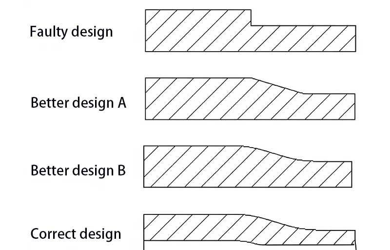
Wall Thickness Uniformity
If there are sudden changes in wall thickness in the design (e.g., an abrupt increase from 2 mm to 5 mm), it will result in significant differences in the cooling rate of the melt, causing defects such as sink marks and warping. The mold needs to be designed with additional complex cooling channels to balance the temperature differences, increasing mold costs. In contrast, uniform wall thickness (e.g., controlled within 1 – 3 mm with a change gradient ≤ 1:3) can simplify the cooling system, reduce the difficulty of mold processing, and shorten the holding time during injection molding, thereby improving production efficiency.
Side Cavity and Undercut Structures
If a product includes features such as internal side cavities and undercuts (e.g., the inner side of the snap-fit on a phone case), the mold needs to incorporate slide blocks, lifters, or core-pulling mechanisms. These structures not only increase mold costs by 30% – 50% but may also lead to dimensional deviations in parts due to the motion errors of the mechanisms. By optimizing the structure during design (e.g., changing the undercut to an external protrusion), complex mechanisms can be avoided, reducing the mold failure rate.
Rib and Boss Design
If the thickness of ribs exceeds 70% of the main wall thickness, sink marks are likely to form on the surface. The mold needs to compensate by increasing the holding time or optimizing the gate location, which extends the molding cycle. On the other hand, a reasonable rib design (with a thickness of 50% – 60% of the main body and a height ≤ 3 times the wall thickness) can enhance structural strength without affecting surface quality, allowing the mold to produce parts stably without additional adjustments.
2. Material Selection and Design Compatibility Affect Molding Stability
The selection of materials in product design needs to match the characteristics of the injection molding process; otherwise, a series of molding problems may arise.
Material Flowability and Structural Matching
When designing slender and thin-walled parts (e.g., a conduit with a diameter of 5 mm and a length of 100 mm), if a material with poor flowability (e.g., glass-fiber-reinforced PA66) is chosen, issues such as filling difficulties and short shots may occur. In such cases, it is necessary to select a high-flow grade material (e.g., PP with an MFR ≥ 20 g/10 min) during the design stage or increase the wall thickness to above 1.5 mm to ensure that the melt can fully fill the cavity.
Shrinkage Rate Control
Crystalline materials (e.g., PE and POM) have a relatively high shrinkage rate (1% – 3%). If a product design includes precision-fitting structures (e.g., a clearance of ≤ 0.05 mm between a gear and a shaft sleeve), failure to consider shrinkage compensation will result in an overly tight fit during assembly. During design, it is necessary to reserve a mold enlargement ratio according to the material’s shrinkage rate (e.g., enlarging the mold size of POM products by 2%) and reduce uneven shrinkage through uniform wall thickness.
Temperature Resistance and Process Matching
If a high-temperature molding material (e.g., PC, which requires a molding temperature of 280 – 300°C) is designed into a complex deep-cavity structure, the melt may degrade due to excessive residence time in the cavity, resulting in black spot defects. In such cases, the deep-cavity structure should be simplified during design, or a multi-gate design should be adopted to shorten the flow path and prevent material degradation.
3. Process-Compatible Design Determines Production Efficiency and Scrap Rate
Product design needs to fully consider the limitations of the injection molding process; otherwise, it will increase the difficulty of debugging and reduce production stability.
Draft Angle and Demolding Feasibility
If a vertical surface has no draft angle (or a draft angle < 0.5°), it will cause friction between the part and the mold cavity during demolding, resulting in scratches or deformation on the part. The scrap rate can be as high as over 20%. By setting a reasonable draft angle according to the surface roughness during design (e.g., ≥ 1° for high-gloss surfaces and ≥ 0.5° for matte surfaces), smooth demolding can be achieved, and the scrap rate can be reduced to below 1%.
Gate Location and Weld Line Control
If the gate location is far from the thick-walled area, weld lines may form at the end of the melt flow, reducing the part’s strength. For example, when designing an automotive bumper, placing the gate at the midpoint of the long side can position the weld lines in non-load-bearing areas. If the gate location is inappropriate, it may need to be compensated for by increasing the injection pressure and extending the holding time, which increases energy consumption and costs.
Venting Design Compatibility
If a closed cavity (e.g., the interior of a watch case) has no reserved venting space, bubbles or scorch marks may form due to gas entrapment. By setting grooves or notches (with a depth of 0.05 mm) at the last filling position of the melt during design, auxiliary venting can be achieved, reducing the need for additional venting slots in the mold and shortening the mold manufacturing cycle.
4. Cost-Oriented Design Optimizes the Overall Economy of the Injection Molding Process
The rationality of product design directly affects the comprehensive cost of injection molding, which is reflected in mold investment, material consumption, production efficiency, etc.
Simplified Structure to Reduce Mold Costs
Multi-component assembled products (e.g., a toy housing composed of three parts) can be redesigned into a single part through integrated design, reducing the number of molds (from 3 sets to 1 set). This can reduce mold costs by over 50% and eliminate the assembly process, improving production efficiency by 30%.
Lightweight Design to Reduce Material Consumption
By optimizing the product structure through CAE analysis (e.g., adopting a hollow design in non-load-bearing areas), the part weight can be reduced by 15% – 20%. The material cost is reduced proportionally, and the cooling time is shortened (due to thinner wall thickness). The molding cycle can be reduced from 30 seconds to 20 seconds, increasing production capacity by 50%.
Standardized Design to Improve Versatility
Unifying the module and interface dimensions of parts (e.g., setting the button diameter of home appliance products to 10 mm uniformly) enables cavity sharing in the mold. A single multi-cavity mold can produce multiple products, increasing mold utilization by 40% and reducing the amortized cost.
Conclusion
Product design is the “source” of injection molding, and its rationality runs through the entire process of mold manufacturing, material selection, process debugging, and cost control. Excellent design can achieve “the best performance at the lowest cost,” while design that ignores the characteristics of the injection molding process will lead to production obstacles and soaring costs. Therefore, introducing the concept of “Design for Manufacturing (DFM)” during the product design stage and strengthening collaboration between the design team and injection molding engineers are essential to achieving a balance between design creativity and mass production feasibility and laying the foundation for efficient and stable injection molding.